 Co., Ltd.")
Vehicle Basic Structure Information
Category:
Key words:
Product Details
1. Main technical parameters and configuration
|
cubic number |
9 square |
10 square |
12 square |
|
geometric volume/cu.m |
16 |
17.4 |
20.2 |
|
Stirring volume/cu.m |
9 |
10 |
12 |
|
Tank mounting angle/ ° |
12.5 |
11.5 |
11 |
|
Feed rate/cu.m/min |
≥2.5 |
≥2.5 |
≥2.5 |
|
Outlet speed/cu.m/min |
≥2 |
≥2 |
≥2 |
|
residual rate/% |
<5% |
<5% |
<5% |
|
stirring speed/rpm |
0~14 |
0~14 |
0~12 |
|
transmission shaft |
Telescopic spline |
Telescopic spline |
Telescopic spline |
|
heat sink |
18L,combined, thermal control |
18L,combined, thermal control |
18L,combined, thermal control |
|
Tank volume L |
450 |
450 |
450 |
|
water system |
air pressure |
air pressure |
air pressure |
|
Electrical system |
24V |
24V |
24V |
|
Labeling assembly |
CIMC tanks, tanks, Fender stickers, warning signs |
CIMC tank, water tank, Fender stickers, warning signs |
CIMC tank, water tank, Fender stickers, warning signs |
|
control system |
Link control |
Link control |
Link control |
|
feeding system |
funnel |
funnel |
funnel |
|
ladder walkway |
Fixed stepped |
Fixed stepped |
Fixed stepped |
|
fender |
Prefabricated steel structure |
Prefabricated steel structure |
Prefabricated steel structure |
|
bumper |
Prefabricated steel structure |
Prefabricated steel structure |
Prefabricated steel structure |
2. Structural characteristics
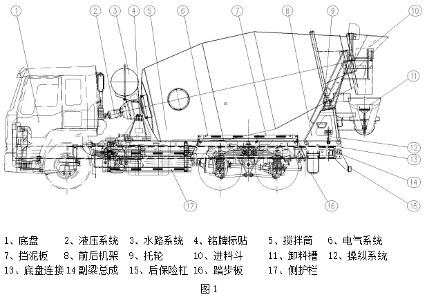
CIMC series concrete mixer trucks are composed of two parts: chassis and bodywork. The chassis is provided by well-known brand car manufacturers at home and abroad. For the specific structure and characteristics, please refer to the "Instruction Manual" provided by each car manufacturer. The upper part is composed of mixing drum, sub-frame, feeding and discharging device, control system, waterway system, electrical system and other accessories. The specific structure is shown in Figure 1.
The front end of the entire mixing drum is installed on the front frame through the reducer, the main bearing of the reducer can be automatically centered, the rear end is supported on the two supporting wheels of the rear frame, and the front and rear frames are fixed on the subframe. By taking power from the PTO port of the engine, the hydraulic pump generates high pressure, and then the high-pressure hydraulic oil drives the hydraulic motor to work, and a low-speed and high-torque reducer drives the mixing drum to work.
In addition to the characteristics of general mixer trucks, CIMC brand mixer trucks also have the following unique features:
1. The large-volume design of the mixing drum enables it to have a larger mixing space, which can better ensure the mixing quality of concrete;
2. The lower center of gravity makes the vehicle more stable when driving;
3. The compact closed hydraulic circuit system has the characteristics of energy saving and high working efficiency;
4. The high-efficiency and energy-saving cooling system and temperature control switch can ensure that the temperature of the hydraulic system is never higher than 65℃;
5. The mixing drum and mixing blades are made of professional wear-resistant materials, and the feed hopper, chute and discharge chute are equipped with wear-resistant linings, which improves the service life of the components;
6. The subframe adopts a box-shaped structure, which increases the torsion resistance of the vehicle;
7. The stirring blades are equipped with wear-resistant protective strips;
8. The raceway of the mixing drum adopts integral die forging, which has good strength and rigidity;
9. The mixing blades are processed by professional molds. The overall structure is logarithmic double helix curve and Archimedes helix curve. It has excellent flow conductivity and mixing performance, so that the quality of concrete is effectively guaranteed.
10. The left and right sides and in the cab (see the detailed configuration of each vehicle) are equipped with control handles, which are convenient, reliable, and highly user-friendly design;
11. The anti-jump device makes it impossible for the mixer truck to jump when it is running on the uneven road without load, protect the supporting rollers and raceways as much as possible, and reduce the noise when the truck is running empty;
12. The large-volume water tank and the multi-channel flushing water system ensure high efficiency when cleaning equipment;
13. The setting of the rear work light ensures the lighting of the equipment when it is working at night.
3. Introduction of main components
1. Mixing drum
The mixing drum (Fig. 2) is the key component of the mixer truck. As a container for storing and mixing concrete, it plays a decisive role in preventing its curing and segregation.
The mixing drum is composed of front cone, middle section, back cone, head, feeding cone, raceway and blades, etc. The front end flange is connected with the reducer, and the raceway of the back cone is supported on the supporting wheel. The curved blade is welded into two 180° symmetrical spiral blade bodies by the combination of logarithmic spiral curve and cylindrical segment Archimedes spiral curve to complete the concrete mixing and loading and unloading operations. In addition, the concrete does not segregate during mixing, so that the concrete can flow evenly in the mixing drum, prolong the initial setting time, improve the homogeneity, and help improve the discharge performance of low slump concrete. With perforations, it can reduce the adhesion of concrete.
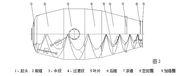
The small feeding cone is funnel-shaped and has a large diameter, which can ensure smooth feeding. The mixing drum is equipped with mixing blades and auxiliary blades, which further improves the mixing performance and is conducive to maintaining the quality of ready-mixed concrete. There are one or two holes on the mixing drum, which is convenient for maintenance and removal of accumulated concrete.
2. Subframe
The subframe is the main load-bearing component. The load during operation is almost all supported by it and then transmitted to the chassis frame. In addition, the impact load formed by the uneven road surface and acceleration and deceleration during driving are all related to the structure of the subframe. High demands were made.
The subframe is mainly composed of front and rear brackets and sub-beam. The front and rear brackets and the sub-beam are respectively assembled and welded to form a part, and then formed into a whole by welding or assembly.
The sub-beam is made of high-strength alloy steel rectangular tube and adopts an integral box-shaped structure, which fundamentally enhances its torsion resistance, bending resistance and tensile strength, and ensures the rigidity requirements. An auxiliary beam is installed between the two main beams to adjust the rigidity of each section of the main beam, so that the load is evenly distributed over the entire length of the subframe.
In the process of driving, it is inevitable to encounter special circumstances and the inertial impact caused by emergency braking. In addition, the mixing drum itself has a certain inclination angle, so the load on the front bracket is relatively much larger, and This part of the load is mainly added to the six bolts connecting the reducer and the front bracket. In order to prevent the bolts from being sheared and accidents, a thrust block is installed on the front bracket table, so that the bolts are not affected by the shearing force and ensure that the bolts are not affected by the shearing force. Safety in vehicle operation. In order to eliminate the influence caused by manufacturing errors, the position of the supporting roller on the rear bracket can be adjusted forward and backward to ensure the contact between the supporting roller and the raceway. After the assembly and debugging are completed, a fixed stop is installed to prevent the supporting roller from being caused by loose bolts. offset.
3. Hydraulic transmission system
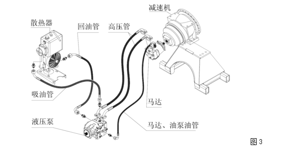
The hydraulic system adopts a typical closed hydrostatic transmission system, which has the characteristics of high efficiency, less heat generation, and low noise. The principle and composition of hydraulic transmission are shown in Figure 3.
The hydraulic transmission system adopts the chassis engine PTO output to take power, the power is transmitted to the variable oil pump through the transmission shaft, the high-pressure oil drives the quantitative motor, and the motor transmits the power to the reducer and drives the mixing drum to rotate forward and reverse to realize feeding, stirring or Discharge.
The variable pump adopts a swash plate structure. The flow rate is proportional to the driving speed and displacement, and the speed can be adjusted steplessly. As the swing angle of the swash plate increases, the flow goes from zero to the maximum value. Smooth steering; one joystick controls direction, shifting and dynamic braking. It enables the operator to accurately control the power of the engine according to the load conditions, so as to achieve the purpose of optimizing performance, improving productivity and saving fuel.
The swash plate quantitative motor, the output speed is proportional to the input flow and inversely proportional to the displacement, the driving torque increases with the increase of the pressure drop on the high pressure side and the low pressure side of the motor, a valve block is installed on the motor, and there are two valve blocks in the valve block. A high pressure relief valve, a shuttle valve and a charge pump pressure valve. When the pressure in the closed-loop oil circuit reaches the limit pressure, the high pressure relief valve acts to prevent the hydraulic system from overloading. The shuttle valve and the charge pump relief valve are used to The motor supplies oil and keeps the oil in the oil circuit refreshed and cooled.
The reducer is a planetary deceleration with low speed and high torque, which can provide excellent output performance and long service life.
The system has an automatic temperature protection device. When the working temperature exceeds 65°C, the temperature control switch is automatically turned on and the cooler starts to work. When the working temperature is lower than 60°C, the temperature control switch is automatically turned off and the cooler stops working, which not only ensures the The normal working temperature of the hydraulic system has achieved the effect of energy saving.
1. Control system
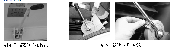
The manipulation can not only control the forward and reverse rotation and speed of the mixing drum, but also control the throttle of the engine. According to different models, there is a joystick or a controller, or two controllers respectively. The cab control is in the form of a push-pull flexible shaft, and the internal and external control systems are interconnected. The driving control also has a locking function to ensure that the vehicle is locked during the driving process. polluted environment.
The operating handle is distributed on the left or both sides of the rear bracket, and by pulling the operating handle, the displacement and direction of the hydraulic oil of the pump can be adjusted, so as to control the feeding and discharging of the mixing drum; when the engine speed needs to be adjusted, the Move the joystick to adjust the throttle of the engine to achieve the purpose of controlling the speed of the mixing drum (Figure 4).
1. Infeed and outfeed assembly
The feeding and discharging assembly is an important part of the mixer truck, which consists of a feeding hopper, a chute, a discharge trough, an extension trough, a support frame and a locking frame.
The feeding hopper and discharge chute are equipped with lining plates to improve the wear resistance. The discharge chute can be rotated 180 degrees in the horizontal direction, and the height can be adjusted in the vertical direction. working condition. When not working or during driving, the discharge chute should be locked on the locking frame to ensure safe driving.
2. Water system
The water system is mainly used for the cleaning of concrete mixer trucks and the provision of mixing water when ready-mixed concrete. The water supply system is usually divided into two types: pressure water supply and water pump water supply. The pressure water supply method is that a pressure water tank is installed above the reducer. The compressed air in the air storage tank of the automobile chassis passes through the pressure reducing valve into the pressure water tank, and the control valve is opened during cleaning. , the high-pressure water flow is sprayed out by itself. The water supply method of the water pump is to form a high-pressure water flow through the water pump, which is used for cleaning and other operations.
Product Inquiry
CIMC Vehicle (Jiangmen) Co., Ltd.
Tel: +86-750-6969888
Fax: +86-750-6969028
Add: No. 67, Xinao West Road, Daao Town, Xinhui District, Jiangmen, Guangdong, China

 WeChat")
Powered by www.300.cn Jiangmen | SEO Tags | This site supports IPv6